
Preferred Design Guidance
The Federal Highway Administration (FHWA) recommended design guidance for column-supported embankments is contained within the publication listed below. However, because new research and tools for the design of CSEs have been developed since the publishing of the FHWA guidance, the design procedure described in this section is recommended.
|
Publication Title |
Publication Year |
Publication Number |
Available for Download |
|---|---|---|---|
| Schaefer, V.R., Berg, R.R., Collin, J.G., Christopher, B.R., DiMaggio, J.A., Filz, G.M., Bruce, D.A., and Ayala, D. “Ground Modification Methods Reference Manual Vol. II” Federal Highway Administration, Washington, DC, FHWA NHI-16-028 (Vol. II), 542p |
2017 |
FHWA NHI-16-028 |
Yes1 |
1 This document is available online at https://www.fhwa.dot.gov/engineering/geotech/pubs/nhi16028.pdf.
This procedure is recommended based on a review of the available literature, documented case histories, and the pilot-scale tests conducted at Virginia Tech for the SHRP 2 R02 project. Note that the terms “bridging layer” and “load transfer platform (LTP)” are used interchangeably and refer to a geosynthetic-reinforced select fill layer within the CSE. The primary references used to develop this procedure are Filz et al. (2019), Schaefer et al. (2017), and the GeogridBridge 3 User and Theory Manuals. Figure 1 shows a basic diagram of a geosynthetic-reinforced column-supported embankment consistent with the procedure that follows. The design procedure applies to both square/rectangular and triangular column arrangements, as shown in Figure 2. Table 1 lists the input and output parameters for the design procedure and defines some of the variables used within the design procedure. Variables not defined within Table 1 are defined within the text of the procedure. Referring to Figure 2 and Table 1, the area replacement ratio, as, is defined as the ratio of the column (or cap) area to the unit cell area.
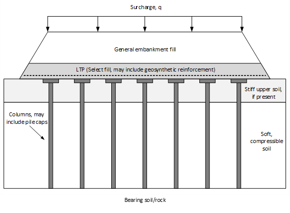
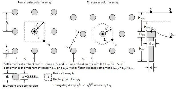
Table 1. Typical inputs and outputs for design and analysis procedures
| Performance Criteria/Indicators |
|
| Subsurface Conditions |
|
| Loading Conditions |
|
| Material Characteristics |
|
| Construction Techniques |
|
| Geometry |
|
References
Aboshi, H., Ichimoto, E., Enoki, M., and Harada, K. (1979). “The Compozer - A Method to Improve Characteristics of Soft Clays by Inclusion of Large Diameter Sand Columns.” Proceedings of International Conference on Soil Reinforcement, pp. 211-216.
Ariyarathne, P., Liyanapathirana, D.S., and Leo, C.J. (2013). “Comparison of different two-dimensional idealizations for a geosynthetic-reinforced pile-supported embankment.” International Journal of Geomechanics, 13(6): 754-768, ASCE, Reston, VA.
Barksdale, R. D. and Bachus, R. C. (1983). “Design and Construction of Stone Columns.” Federal Highway Administration, Washington, DC, FHWA RD-83-027 (Vol. II).
Berg, R.R., Christopher, B.R. and Samtani, N.C. (2009). “Design of Mechanically Stabilized Earth Walls and Reinforced Soil Slopes.” Geotechnical Engineering Circular No. 11 (GEC 11). Federal Highway Administration, Washington, DC, FHWA-NHI-10-024. 332p. https://www.fhwa.dot.gov/engineering/geotech/pubs/nhi10024/nhi10024.pdf
British Standards Institution. BS8006 (2010). Code of Practice for Strengthened/Reinforced Soils and Other Fills. London, U.K.
Broms, B.B. (1991). “Stabilization of soil with lime columns.” Foundation Engineering Handbook.
Brown, D. A., Dapp, S. D., Thompson, W.R., and Lazarte, C.A. (2007). “Design and Construction of Continuous Flight Auger (CFA) Piles.” Geotechnical Engineering Circular No. 8 (GEC 8). Federal Highway Administration, Washington, DC, FHWA HIF-07-03. 293p. https://www.fhwa.dot.gov/engineering/geotech/pubs/gec8/gec8.pdf
Collin, J.G. (2004). “Column supported embankment design considerations.” 52nd Annual Geotechnical Engineering Conference- University of Minnesota.
Collin, J.G. (2002). “Timber Pile Design and Construction Manual.” Timber Piling Council, American Wood Preservers Institute.
Collin, J.G. (2007). “U.S. state-of-practice for the design of geosynthetic reinforced load transfer platforms in column supported embankments.” GeoDenver 2007.
Duncan, J.M., Brandon, T., Jian, W., Smith, G., Park, Y., Griffith, T., Corton, J., and Ryan, E. (2007). “Densities and friction angles of granular materials with standard gradations 21b and #57.” Report of a testing program performed by the Virginia Tech Center for Geotechnical Practice and Research. 92 p.
Duncan, J.M., Wright, S.G., and Brandon, T.L. (2014). Soil Strength and Slope Stability. John Wiley & Sons.
Filz, G. M. and Smith, M. E. (2006). Design of Bridging Layers in Geosynthetic-Reinforced, Column-Supported Embankments. Report No. VTRC 06-CR12, Virginia Transportation Research Council, Charlottesville, Virginia.
Filz, G. M. and Navin, M. P. (2006). “Stability of column-supported embankments.” Virginia Department of Transportation, VTRC 06-CR13.
Filz, G.M. and Templeton, E. (2009). Design Guide for Levee and Floodwall Stability Using Deep-Mixed Shear Walls, prepared by Burns Cooley Dennis for the U.S. Army Corps of Engineers.
Filz, G. M., Sloan, J. A., McGuire, M. P., Smith, M., Collin, J. (2019) “Settlement and Vertical Load Transfer in Column-Supported Embankments.” J. Geotech. Geoenviron. Eng., 145(10): 04019083.
https://doi.org/10.1061/(ASCE)GT.1943-5606.0002130.
Goughnour, R. R., Sung, J. T., and Ramsey, J. S. (1991). “Slide Correction by Stone Columns.” Deep Foundation Improvements: Design, Construction, and Testing, ASTM STP 1089, Philadelphia, 1991, pp. 131-147.
Griffiths, D.V. and Lane, P.A. (1999) Slope Stability Analysis by Finite Elements. Geotechnique, 49, 387-403. http://dx.doi.org/10.1680/geot.1999.49.3.387.
Han, J., Wang, F., Al-Naddaf, M., and Xu, C...(2017). “Progressive development of two-dimensional soil arching with displacement.” Int. J. Geomech.17(12): 04017112.
Hannigan, P.J., Rausche, F., Likins, G.E., Robinson, B.R., and Becker, M.L. (2016). “Design and Construction of Driven Pile Foundations.” Geotechnical Engineering Circular No. 12 (GEC 12). Federal Highway Administration, Washington, DC, FHWA FHW A-NHI -16-009. 563p.
Huang, Z., Ziotopoulou, K., and Filz, G.M. (2020). “Lateral Thrust Distribution of Column-Supported Embankments for Limiting Cases of Lateral Spreading.” J. Geotech. Geoenviron. Eng., 146(11): 04020126. https://doi.org/10.1061/(ASCE)GT.1943-5606.0002375.
Janbu, N. (1963). “Soil compressibility as determined by oedometer and triaxial tests.” Proceedings, European Conference on Soil Mechanics and Foundation Engineering, Wiesbaden, Vol. 1. pp. 19 - 25 and Vol. 2, pp. 17 - 21.
King, D.J., Bouazza, A., Gniel, J.R., Rowe, R.K., and Bui, H.H. (2017). “Load-transfer platform behavior in embankments supported on semi-rigid columns: implications of the ground reaction curve.” Geotextiles and Geomembranes, 54(8).
McGuire, M. P. (2011). “Critical height and surface deformation of column-supported embankments.” PhD Dissertation, Virginia Polytechnic Institute and State University, Blacksburg.
McGuire, M. P. and Filz, G. M. (2010). “Incorporation of slack and creep in the British Standard code of practice for calculating tension and deflection of geosynthetic reinforcement used in column-supported embankments.” Proceedings, 9th International Conference on Geosynthetics, Brazil, pp. 1945-1948.
McGuire, M. P., Hunstein, E. M., Hummel, E. G., Sloan, J. A. (2022). “Theory Manual for GeoGridBridge 3.0.”
McGuire, M. P., Hummel, E. G., Hunstein, E. M., Sloan, J. A. (2022). “User Manual for GeogridBridge 3.0.”
McGuire, M. P., Sloan, J. A., Hunstein, E. M., Socolofsky, L. (2022). “The Ground Reaction Curve and Mobilization of Soil Arching in Geosynthetic-Reinforced Column-Supported Embankments.” Proceedings, Geo-Congress 2022: Soil Improvement, Geosynthetics, and Innovative Geomaterials, pp. 508-519.
Poulos, H.G. and Davis, E.H. (1973). Elastic Solutions for Soil and Rock Mechanics. John Wiley & Sons.
Rogbeck, Y., Alen, C., Franzen, G., Kjeld, A., Oden, K., Rathmayer, H., Want, A., and Oiseth, E. (2003). “Nordic guidelines for reinforced soils and fills.” Nordic Geosynthetic Group of the Nordic Geotechnical Societies, Nordic Industrial Fund.
Russell, D., and Pierpoint, N. (1997) “An assessment of design methods for piled embankments.” Ground Engineering. 30(11): 39-44.
Schaefer, V.R., Berg, R.R., Collin, J.G., Christopher, B.R., DiMaggio, J.A., Filz, G.M., Bruce, D.A., and Ayala, D. (2017b). “Ground Modification Methods,” Federal Highway Administration, Washington, DC, FHWA NHI-16-028 (Vol. II), 542p. https://www.fhwa.dot.gov/engineering/geotech/pubs/nhi16028.pdf
Sloan, J.A., Filz, G.M., and Collin, J.G. (2012). "Task 10 Report. Column-Supported Embankments: Field Tests and Design Recommendations," a publication of the Strategic Highway Research Program, Project SHRP2 R02, Transportation Research Board of The National Academies, Washington, D.C.
Spencer, E. (1967). A method of analysis of the stability of embankments assuming parallel interslices forces. Geotechnique 17(1), 11-26.
Recommended Design Procedure
- Collect project information, including the required embankment height, H, the traffic surcharge loading, q, and the maximum allowable post-construction embankment surface settlement, Ss,pc. The embankment height will be determined by elevation of the existing subgrade and the required final elevation of the finished road surface. Typically, q = 250 to 300 psf, but q may vary depending on the application. According to Schaefer et al. (2017), CSE technology typically reduces post-construction settlement of the embankment surface to less than 2 to 4 inches (50 to 100 mm). The allowable total settlement will depend on the type of application, the embankment height, and the embankment fill properties. An allowable total surface settlement of 3 inches (75 mm) is recommended here.
- Collect subsurface information, including stratigraphy, field test data, laboratory test results, and ground water information. Develop subsurface profile(s) for design.
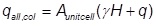
- Given the embankment height, surcharge loading, and subsurface profile (depth and soil type), select the preliminary column type(s) based on typical column capacities, lengths, diameters, and whether soil displacement by the column is desired/acceptable. The columns should be designed to carry the entire embankment load. To be consistent with subsequent steps of the design procedure, it is not recommended that the column be designed for a partial embankment load determined using numerical models for unit cell analysis. Therefore, the allowable column load, qall,col, is:
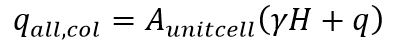
where,Aunitcell = Tributary area of the column as defined in Figure 2
γ = Unit weight of the embankment fill
H = Embankment height
q = Embankment dead and live load surcharge
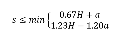
In conjunction with selecting the preliminary column type(s), select trial values of the maximum center-to-center column spacing, s, of the columns and the minimum column diameter, dcol, or pile cap width, a, to satisfy the following criteria obtained from a synthesis of recommendations in the literature:
- The embankment height, H, must be greater than the critical height, Hcrit. The critical height is the minimum height at which there is zero differential settlement for a given column diameter, spacing, and arrangement. The results of field-scale tests presented in Sloan et al. (2012) agree with the relationship for Hcrit developed by McGuire (2011), Hcrit = 1.15 s' + 1.438 dcol, where s’ is defined in Figure 2. For square column arrays, there is also agreement for the more conventional relationship of Hcrit = 1.5 (s - a) and the equation that results in the larger predicted critical height of the two relationships is recommended. For square arrays:
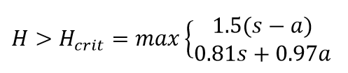
Generally, the embankment height is fixed by the existing subgrade elevation and the required road or highway elevation, including allowance for anticipated settlement. For a given column or pile cap width, a, the minimum square column center-to-center spacing, s, for a square array can be found according to:
Note that subgrade support tends to reduce differential surface settlements and traffic loading tends to increase differential surface settlements, so these effects tend to offset each other. If there is no significant subgrade support, the designer may elect to increase the critical height by 15% to 20%.
- According to Collin (2004) and Schaefer et al. (2017):
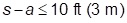
Note that an equivalent area conversion between round and square column and pile cap shapes defined in Figure 2 can be applied in this step if needed.
- The embankment height, H, must be greater than the critical height, Hcrit. The critical height is the minimum height at which there is zero differential settlement for a given column diameter, spacing, and arrangement. The results of field-scale tests presented in Sloan et al. (2012) agree with the relationship for Hcrit developed by McGuire (2011), Hcrit = 1.15 s' + 1.438 dcol, where s’ is defined in Figure 2. For square column arrays, there is also agreement for the more conventional relationship of Hcrit = 1.5 (s - a) and the equation that results in the larger predicted critical height of the two relationships is recommended. For square arrays:
- Choose the select fill for the load transfer platform. Collin (2004) and Schaefer et al. (2017) recommend a material with an effective friction angle of at least 35°. The gradation requirements are as follows:
Size Percent Passing 200 mm (4 in.) 100 4.75 mm (No. 4) 15 to 70 0.425 mm (No. 40) 10 to 60 0.075 mm (No. 200) 5 to 15 Due to the wide range of acceptable gradations for the criteria above, and the desire for a well-graded material to provide strength and promote arching, the select fill should also have:
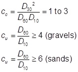
where,
cc = Coefficient of curvature
cu = Coefficient of uniformity
cc and cu are determined from the gradation curve. Reinforced fill material passing the No. 40 sieve shall have a liquid limit less than 40 and a plasticity index less than 20.
If the proposed fill material meets these criteria, estimate values of unit weight, friction angle, modulus, and Poisson’s ratio. The large-strain effective stress friction angle should be used for design. Triaxial tests by Duncan et al. (2007) on VDOT 21B dense-graded aggregate produced peak friction angles that varied from 48° to 58° and occurred at axial strains of 2 to 5% for confining pressures from 6 to 30 psi. At the same confining pressures, the friction angles at axial strains of 8 to 11% were only slightly smaller and varied from 46° to 53°. Therefore, the estimated large-strain friction angles for select gravel fill used for design can be quite large.
The minimum thickness of the LTP should be 2 feet to ensure efficient load transfer. Typical thicknesses range between 2 and 4 feet.
- Determine the embankment fill material that will be used above the bridging layer. This may be any suitable material for embankment construction. Estimate the values of unit weight, friction angle, modulus, and Poisson’s ratio for this material.
- Design the columns or piles to be able to carry the entire load from the embankment and surcharge with an adequate factor of safety. LRFD design methodology is acceptable with appropriate load and resistance factors; however, AASHTO currently does not cover a variety of formed-in-place columns, e.g. CFA columns, in LRFD format. Each column should be designed to carry an allowable load of:
where Aunitcell is defined in Figure 2 based on the square/rectangular or triangular column arrangement. Multiple column types may be suitable for a particular set of project conditions, and the column cost may be the determining factor in the column selection process.
Design, QC/QA, specification, and cost estimating guidance for aggregate columns, vibro-concrete columns, and continuous flight auger (CFA) piles are provided in Geotechtools in the “Guidance and Selection System” under their respective technology categories. Some additional information on column design, including traditional piles, is provided below.
- The design of concrete, steel, and timber piling is well established. Design guidelines have been developed by FHWA and may be found Geotechnical Engineering Circular No. 12. (GEC-12) (Hannigan et al. 2016).
- For the design of timber piles, the reader is also referred to Timber Pile Design and Construction Manual, Timber Piling Council (AWPI 2002).
- Aggregate columns are addressed in FHWA GEC 13 (Schaefer et al. 2017) in addition to the guidance in GeoTechTools.
- Guidelines for design of continuous flight auger (CFA) piles and drilled displacement piles (DDPs, also known as rigid inclusions) are found in FHWA GEC-8 (Brown et al. 2007).
- Geosynthetic reinforcement may be used within the LTP to enhance vertical load transfer the columns, increase resistance to lateral spreading, and/or increase global stability. There is ongoing debate regarding how significant the contribution of the reinforcement is to these functions; however, the contribution of geosynthetic to vertical load transfer is usually small, particularly when stiffer soils overlie the soft ground. In some cases, no geosynthetic reinforcement is needed to achieve acceptable settlement and stability.
To evaluate the strength requirements of the reinforcement, let:
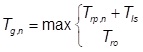
Trp = the tension in the reinforcement due to vertical load transfer to the columns
Tls = the tension in the reinforcement due to resistance against lateral spreading of the embankment
Tro = the tension in the reinforcement due to a contribution to global stability
Tg = the required design tensile strength of the reinforcement
Ta = the long-term allowable tension in the reinforcement in the direction under consideration, i.e. normal or parallel to the centerline of the embankment.
Tult = the ultimate short-term tensile strength of the reinforcement (Minimum Average Roll Value, MARV) in the direction under consideration, i.e. normal or parallel to the centerline of the embankment.
Tcr,5% = the creep-reduced tensile strength of the reinforcement at a 5% serviceability limit strain in the direction under consideration, i.e. normal or parallel to the centerline of the embankment.
>RFD = Durability reduction factor. RFD is dependent on the susceptibility of the geosynthetic to attack by microorganisms, chemicals, thermal oxidation, hydrolysis, and stress cracking. The typical range is from 1.1 to 2.0.
>RFID = Installation damage reduction factor. RFID can range from 1.05 to 3.0, depending on backfill gradation and product mass per unit weight.
>RFCR = Creep reduction factor. RFCR is the ratio of the ultimate strength (Tult) to the creep-limited strength at the ultimate strain obtained from laboratory creep tests for each product. The typical range depends primarily on the polymer composition of the product with 1.6 to 2.5 typical for polyester products, 4.0 to 5.0 typical for polypropylene products, and 2.6 to 5.0 for high-density polyethylene products.
FSUNC = Overall factor of safety or load factor reduction to account for uncertainties in the geometry of the structure, fill properties, reinforcement properties, and externally applied loads.
n = A subscript added to indicate the direction normal to the centerline of the embankment
p = A subscript added to indicate the direction parallel to the centerline of the embankment
Step 8 covers the evaluation of the tension due to vertical load transfer, Step 11 covers the evaluation of lateral spreading of the embankment, and Step 13 covers global stability analysis.
The procedure described herein for design of the reinforcement assumes that either the machine and cross machine direction of the reinforcement are aligned with the centerline of the embankment. Step 14 describes the recommended orientations and vertical spacing of reinforcement for LTPs with single or multiple layers of reinforcement. For LTPs with multiple layers of reinforcement, it may be assumed for practical purposes that the combined strength of the layers in each direction is equal to the sum of the strength of the individual layers in each direction.
This procedure does not consider the possibility for extrusion of foundation soil between the columns or lateral thrust from earth pressures below the reinforcement. Huang et al. (2020) describes numerical modeling that showed some increase in reinforcement tension due to lateral thrust from soils below the reinforcement. For reinforcement common to US practice, the increase in tension was found to be small.
BS8006 (2010) evaluates the strength requirement for geosynthetic reinforcement considering the maximum value of: the force mobilized for global stability or the sum of the tensile forces mobilized to resist lateral spreading and vertical load transfer. For the reinforcement aligned normal to the centerline of the embankment,
For the reinforcement aligned parallel to the centerline of the embankment,

The long-term allowable strength is established to avoid exceeding the creep-reduced tensile strength of the reinforcement at a 5% serviceability limit strain and avoid rupture with a factor of safety:
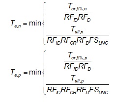
The short-term ultimate strength, Tult, is typically obtained from the geosynthetic product data sheet provided by the manufacturer and the creep-limited strength of the reinforcement at 5% strain, Tcr,5%, can be interpreted from isochronous creep curves corresponding to the design life of the embankment. For an LTP having multiple layers of reinforcement, Tult and Tcr,5% are the combined values estimated by summing the strengths from the individual layers in the reinforcement direction under consideration. Guidelines for determining specific values for the reduction factors (RFD, RFID, RFCR) used in design are found in FHWA GEC 11 (Berg et al. 2009). For load transfer platforms, a minimum overall factor of safety, FUNC, equal to 1.5 is typical.
The required tensile strength of the reinforcement normal and parallel to the embankment centerline must be less than or equal to the long-term allowable strength in each respective direction.

- To evaluate the tension developed in the reinforcement due to vertical load transfer, Trp, select preliminary values for the combined long-term tensile stiffness geosynthetic reinforcement across each column span, J1 and J2. Column spans, c1 and c2, are defined in Figure 3 based on either rectangular or triangular unit cell geometries (red-hashed areas) that have equivalent area as those defined in Figure 2. If reinforcement will not be used for vertical load transfer, J1 and J2 can be considered equal to zero. It is assumed that the spans are aligned normal and parallel to the centerline of the embankment.
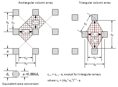
Figure 3: Definition sketch for reinforcement spans for rectangular and triangular column arrangements For a 5% serviceability limit on reinforcement strain, the long-term tensile stiffness of the reinforcement normal and parallel to the centerline of the embankment is estimated by
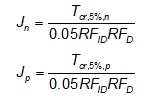
This approach assumes that the reinforcement can be approximated as being linear elastic over the range of strain expected in service. If the span c1 is aligned perpendicular to the embankment centerline,

otherwise,

Perform a settlement analysis using the Load Displacement Compatibility (LDC) method as implemented in the Microsoft Excel® spreadsheet GeogridBridge 3.0 (GGB3) available for download below. Users are advised to use a fresh copy of the spreadsheet for each new analysis. The original version of the spreadsheet was developed by Filz and Smith (2006) and was updated by Sloan et al. (2012). GeogridBridge 3.0 is a completely new version of the spreadsheet available since 2022. A brief description of the LDC method is included in the “Summary of Design/Analysis Procedure” section of this document. The LDC method was selected based on analysis of available information in the literature and the results of field tests conducted for the SHRP 2 R02 project. Additional details on the Excel spreadsheet and an extensive description of the LDC method can be found in the GGB3 Theory and User manuals, which are available for download below. Material property values for use in GGB3 can be found in the attached material properties document developed for a previous version of the spreadsheet, GeogridBridge 2.0.
GeogridBridge 3.0 (GGB3) spreadsheet GGB3 User Manual GGB3 Theory Manual Material Properties Document The workbook calculates the tension in the geosynthetic due to the embankment vertical loads for both spans, c1 and c2, which can be translated to tension normal and parallel to the embankment centerline, Trp,n and Trp,p, based on the orientation of each span. The value of Trp in each reinforcement direction should be compared to the allowable strength as described in Step 7.
-
Interpret the GeogridBridge 3.0 analysis from Step 8 for settlement. The average embankment surface settlement, Ss is defined as the sum of the embankment compliance, SE, the compression of the columns, SC, and the compression of material below the neutral plane, SU, if significant. GeogridBridge3 assumes there is no compression of material below the neutral plane, and therefore the spreadsheet output Ss considers only the compression of material above the neutral plane. The value of SU can be determined using established methods for estimating settlement of pile groups, such as the equivalent footing method the approach of Broms (1991), in which the embankment load is transferred to the bottom of the columns and then distributed with depth using a 1H:2V load spread below the bottom of the columns. Other equivalent footing methods are also acceptable.
The embankment surface settlement, Ss, determined this way represents the average settlement of the pavement surface. The differential settlement of the pavement surface should be small if the criteria and details in Steps 3 and 4 are properly addressed. If a significant time period elapses between the mid-point of embankment construction and pavement placement, Janbu’s (1965) method can be used to estimate the portion of the embankment settlement that occurs before the pavement is constructed. GGB3 computes this settlement and subtracts it from the total embankment settlement to obtain the post-construction settlement of the pavement, Ss,pc.
- Repeat Steps 8 and 9 to refine the GGB3 analyses of reinforcement mobilization for vertical load transfer and settlement until the performance criteria are satisfied without excessive conservatism. Excessive settlement and/or reinforcement tension can be addressed through one or more changes such as using a higher area replacement ratio, stiffer geosynthetic reinforcement, stiffer columns, and/or a preload.
-
Evaluate the potential for lateral spreading, i.e. sliding, of the edge of the embankment. BS8006 (2010) assumes that the earth pressure forces acting to cause lateral spreading can be represented by the active condition. Calculate the tension in the geosynthetic reinforcement due to the tendency of the embankment to spread laterally and find the required bond length at the embankment side slopes, as in BS8006 (2010). Numerical analyses performed by Huang et al. (2020) show that the development of arching within the embankment increases earth pressures above the active condition. Assuming that the assumption of active pressures is adequate, the force acting to cause lateral spreading can be found by:
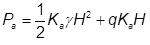
where,
Ka = Active earth pressure coefficient of the embankment fill
γ = Unit weight of embankment fill
H = Full embankment height
q = Embankment surcharge
If no reinforcement is implemented, a portion of sliding forces will be transferred to the columns due to bending resistance as represented by the lateral load-deflection relationship, i.e. p-y relationship, of the columns and soil. Depending on the stiffness of the p-y relationship, the column area replacement ratio, and the shear displacement required to mobilize shearing resistance in the subgrade soils, the columns may attract a significant portion of the sliding force. In these cases, the columns should be designed with consideration of lateral loading. Given the uncertainty regarding the portion of the sliding force that is carried by the columns over their service life, adequate resistance should be available by the subgrade soils alone over the horizontal distance from the shoulder to the toe of the embankment, Ls, as shown in Figure 4 when no reinforcement is used to resist sliding.

where,
τf = Interface shear strength between the embankment and subgrade soil along Ls
If the subgrade is expected to be undrained in the short term, as would be expected for a silt or clay soil, the undrained strength should be considered. If the subgrade is expected to be drained in the short term, as would be expected for a sand or gravel soil, the drained strength should be considered. A minimum factor of safety of 1.5 is recommended for resisting lateral spreading of the embankment. If an adequate factor of safety cannot be obtained, geosynthetic reinforcement can be used as described below.
If reinforcement is implemented, Schaefer et al. (2017) recommend that the reinforcement be designed to carry the entirety of Pa. This means that the design tension in the reinforcement due to lateral spreading perpendicular to the centerline of the embankment, Tls, is equal to Pa. Referring to Figure 4, the minimum bond length, Le, of the reinforcement beyond the shoulder of the embankment, i.e. at the edge of the crest, necessary to develop the required strength without the side slope of the embankment sliding across the reinforcement is determined by:
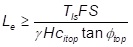
where,
citop= Interaction factor (Berg et al. 2009) for sliding between the reinforcement and fill above the reinforcement. In the absence of project-specific information, an interaction factor equal to 2/3 is recommended for geosynthetic reinforcement.
ϕtop = Friction angle of the embankment fill above the reinforcement
FS = Factor of safety for lateral sliding development length (a minimum value of 1.5 is recommended)
γ = Unit weight of embankment fill
H = Average height of the embankment above the reinforcement length, Le
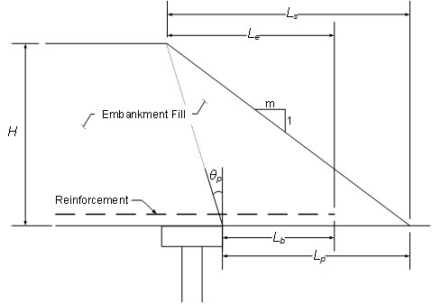
Figure 4. Definition of Ls, Le, Lb, Lp, and θp In addition to checking that the reinforcement develops an adequate bond with the overlying embankment soil to provide resistance to lateral spreading, the resistance to pullout from the forces resisting lateral spreading and vertical load transfer must also be checked. Referring again to Figure 3, the minimum bond length of the reinforcement, Lb, with the soil immediate above and below to resist pullout forces, is determined by:
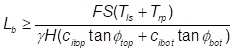
where,
citop= Interaction factor (Berg et al. 2009) for sliding between the reinforcement and fill above the reinforcement. In the absence of project-specific information, an interaction factor equal to 2/3 is recommended for geosynthetic reinforcement.
ϕtop = Friction angle of the embankment fill above the reinforcement
cibot= Interaction factor (Berg et al. 2009) for sliding between the reinforcement and fill below the reinforcement. In the absence of project-specific information, an interaction factor equal to 2/3 is recommended for geosynthetic reinforcement.
ϕbot = Friction angle of soil below the reinforcement
FS = Factor of safety for lateral sliding development length (a minimum value of 1.5 is recommended)
γ = Unit weight of embankment fill
H = Average height of the embankment above the reinforcement length, Lb
- Determine the extent of the columns required across the embankment width to protect the crest from effects from edge instability and/or differential settlement of the side slope. BS8006 (2010) recommends that the maximum horizontal distance between the outer edge of the pile cap or column and the toe of the embankment, Lp, (see Figure 4) be calculated as follows:
where,
H = Embankment height
m = Side slope of the embankment (i.e., mH:1V slope)
θp = Angle in degrees from the vertical between the outer edge of the outside pile cap and the crest of the embankment. BS8006 (2010) recommends:

where,
ϕ = Friction angle of the general embankment fill
The distance Lp should be met by extending the columns further beyond the crest of the embankment instead of steepening the side slope, unless stability checks of the side slope indicate that the slopes can be steepened while maintaining an adequate factor of safety.
The global stability of the embankment side slopes should be checked using the guidance presented in Step 13. Extrusion of the foundation is also a possibility when the foundation soil is very soft. The potential for extrusion increases as the embankment height increases, the thickness of the soft soil decreases, the spacing of the columns increases, and the shear capacity of the columns decreases. In cases where extrusion is a concern, it is recommended to use the procedure in BS8006 (2010) to evaluate the potential for extrusion without considering a stabilizing effect of the columns.
- Check global stability the embankment, including side slopes, using limit equilibrium (LE) procedures. Currently, there is not a generally-accepted procedure for analyzing the stability of column-supported embankments; however, there are analysis recommendations based on column type:
- Global stability for embankments on driven piles: BS8006 (2010) assumes that the piles in a column-supported embankment carry the full vertical embankment load and do not carry any lateral forces. If included, the geosynthetic reinforcement can develop tension as is typical in reinforced slope stability analysis. In cases where geosynthetics are not used and increased stability is needed, battered piles may be used to resist lateral forces. This method is also summarized by Filz and Navin (2006). As described, this method only satisfies moment equilibrium and cannot be easily implemented in slope stability software.
- Global stability for embankments on stone columns: Filz and Navin (2006) summarize the Circular Sliding Surface Method from Aboshi et al. (1979), the Average Strength Parameter Method from Goughnour (1991), and the Profile Method from Barksdale and Bachus (1983). The Profile Method is recommended for use with commercial slope stability software.
- Global stability for embankments on vibro-concrete columns: Key references include the SHRP 2 R02 documentation for vibro-concrete columns
When geosynthetic reinforcement is included in the global stability analysis, it is recommended that Method A as defined by Duncan et al. (2014) be used to incorporate the resistance provided. According to Method A, the allowable long-term tensile strength of the reinforcement is applied within the analysis to reduce the shear stress along the failure surface required for equilibrium. Method A is in contrast with Method B, where the long-term design strength, i.e. the ultimate strength with reduction factors included but no factor of safety, is applied within the stability analysis to add to the available shear strength along the failure surface. In Method B, the global factor of safety, i.e. factor of safety applied to soil shear strength, is also applied to the reinforcement, while in Method A, the factor of safety is applied when evaluating the allowable strength. The use of Method A is compatible with Step 7 to evaluate the strength requirements of the reinforcement. Most commercial slope stability software has the ability for the user to apply either Method A or Method B.
When evaluating global stability, it is important to perform a comprehensive search for the most likely failure surface as well as potentially less likely, but more consequential, failure surfaces. For example, side slope stability may be more likely to occur, but is usually less consequential compared to deep-seated instability. A comprehensive search also includes consideration of failure surfaces having different constraints on shape. Circular failure surfaces are commonly the default option in commercial software, but wedge-shaped surfaces and more complex non-circular surfaces should also be explored. For embankments that incorporate MSE walls, compound stability should be evaluated. Coordination between designers of the MSE walls and column-supported embankment is important to achieve a holistic evaluation of stability.
Global stability analyses should be performed for short-term and long-term conditions. In the short-term, low permeability clay and silt soils should be considered undrained. Pore pressures for soils considered drained in the short and/or long term should be carefully evaluated.
Given that all LE methods require assumptions to be statically determinate, it is recommended that more than one method be relied upon to evaluate stability. Full equilibrium methods, such as Spencer’s Method (1967), are generally the most accurate (Duncan et al. 2014) and should be included as part of the global stability analysis.
Numerical methods, such as the Strength Reduction Factor (SRF) method (Griffiths and Lane, 1999), provide a useful tool for evaluating global stability, including modes of failure that are too complex to represent by traditional LE methods (Filz and Navin, 2006). When the critical failure mode is too complex to be represented, LE methods can overestimate the factor of safety. For plane strain analyses, there are several ways to represent the three-dimensional (3D) array of discrete columns in two dimensions (2D). Ariyaranthne et al. (2013) compared different 2D idealizations and found that preserving the 3D area replacement ratio in 2D and using the actual column properties compared well with results from three-dimensional analyses and field measurements. One limitation of the SRF method is that noncritical failure modes cannot be readily explored. This underscores the value of performing LE analyses as part of a comprehensive assessment of global stability.
It is recommended that the column-supported embankment be designed for a minimum factor of safety equal to 1.5. Higher factors of safety should be used when the consequences of failure are higher than typical and/or there is high uncertainty regarding material properties and loads.
-
Develop the geosynthetic details:
- There are two options to reduce or eliminate abrasion between the columns and the base layer of geosynthetic reinforcement:
- Sections of non-woven geotextile with a minimum weight of 8 oz. may be cut and placed over the top of the columns or pile caps and subgrade soil, with the lowest layer of geosynthetic reinforcement placed directly on top of the non-woven geotextile. A continuous layer of geotextile may be used if a separation function is desired. This method can be applied in any case, and it is the preferred method if the subgrade is weak and mixing of the reinforced fill and subgrade soil will occur without the non-woven geotextile at the interface of the two soil types.
- Where the subgrade is strong enough to prevent mixing of materials, the bottom layer of geosynthetic may be placed on a lift of compacted LTP material at a height of 6 in. above the top of the columns or pile caps.
- Each additional layer of geosynthetic above the base layer should be separated from the underlying layer of geosynthetic by a 6 to 12 inch lift of compacted bridging layer material.
- If multiple layers of biaxial geosynthetic reinforcement are used, the roll directions should be alternated for each additional layer of geosynthetic reinforcement so that the overlying layer is placed perpendicular to the layer beneath it for overlap considerations. If uniaxial geosynthetics are used, two perpendicular layers may be used to act as one biaxial layer.
- Adjacent layers of geogrid reinforcement should be overlapped sufficiently to transfer tension from one roll to the next. A minimum overlap of 3 feet is recommended. If geotextiles are used, the seam between adjacent rolls should be sewn. In this case, the strength of the seam will govern the design strength of the geosynthetic for loading perpendicular to the seam.
- The roll width should be wide enough so that the entire roll width does not fall between columns; some portion of every roll should fall on top of a column. To meet this criteria, the roll width should be selected such that:

where,
w = Geosynthetic roll width
v = Geosynthetic overlap
s = Column center-to-center spacing
- There are two options to reduce or eliminate abrasion between the columns and the base layer of geosynthetic reinforcement:
- Prepare construction drawings and specifications. Guidance for QC/QA and specifications for CSEs are provided in separate documents located within the SHRP 2 R02 Guidance and Selection System.